
Step 3: Wiring
Two jobs: bring pack voltage to the gimbal and the air unit, and bring two signal wires from the flight controller to the gimbal. Nothing gets soldered to the flight controller.
How everything connects
Section titled “How everything connects”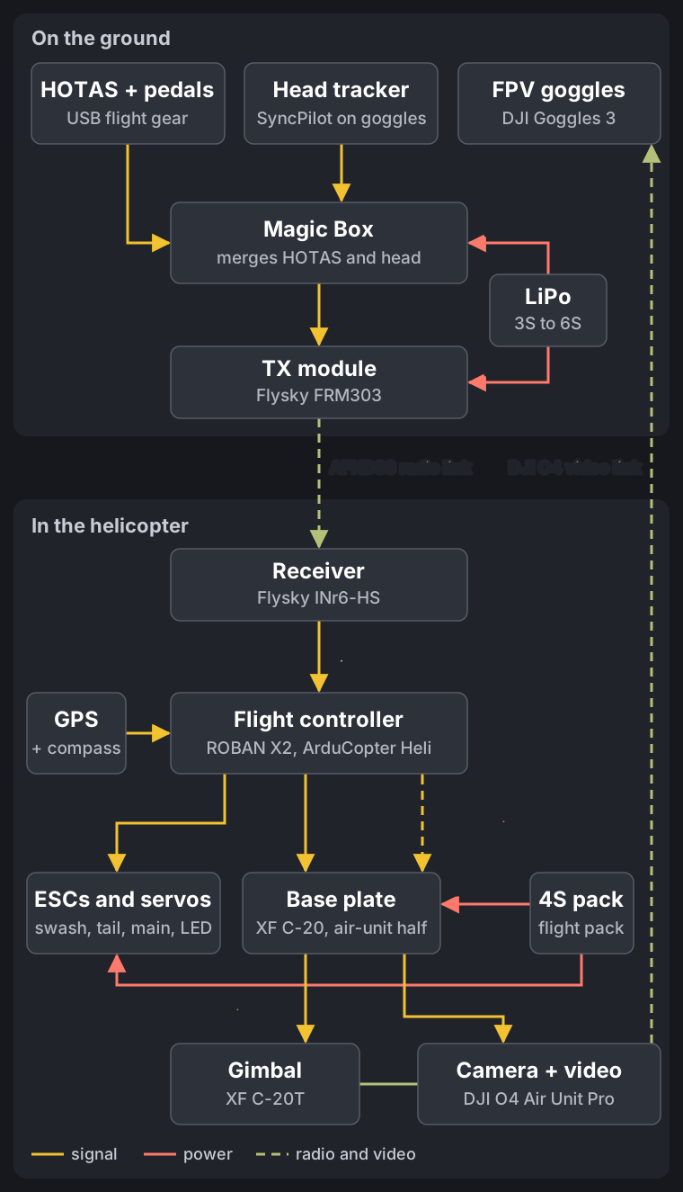
Tap the diagram to open it full size.
Bench first
Section titled “Bench first”Keep everything on the desk for now. Wire it here, then set up Magic Box (step 4) and the flight controller (step 5). Activate the air unit in DJI Assistant 2 and pair it with the goggles. When the camera follows your head, go back to step 2.
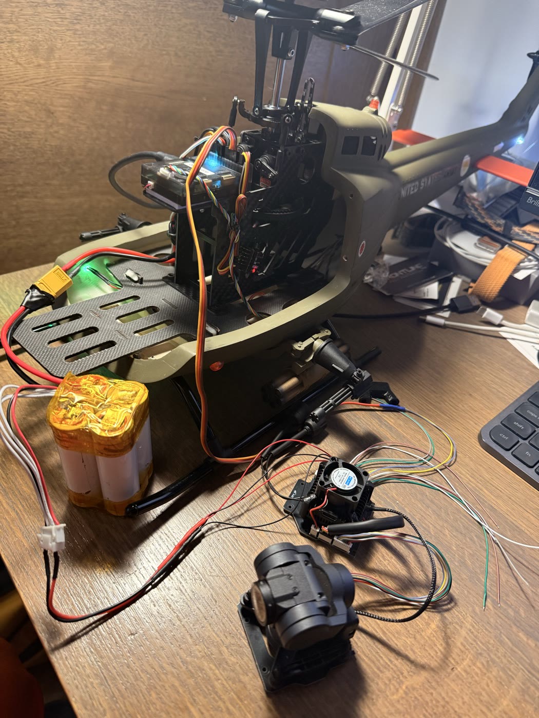
Identify the wires
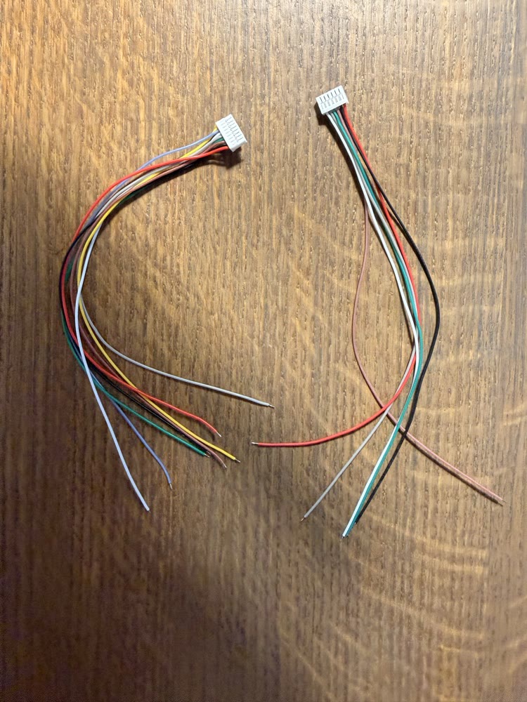
Section titled “Identify the wires”The base plate comes with two pigtails: 8 wires for port 1 and 6 wires for port 2. Wire colours aren’t proof. With both plugged into the plate, use a multimeter on continuity against the “G” pin of the 5 V fan connector:
- On the 8-wire cable one wire beeps: pin 2, GND.
- On the 6-wire cable two wires beep: pins 2 and 5, GND.
- The outer wire next to GND is pin 1, Power In. The rest follow in order.
| Cable | Pin | Connect to |
|---|---|---|
| Port 1 (8-wire) | 1 Power In, 2 GND | 4S pack |
| 3, 4, 5, 6 | Insulate, not used | |
| 7 PWM3 (pitch) | Flight controller output 10, signal | |
| 8 PWM4 (yaw) | Flight controller output 9, signal | |
| Port 2 (6-wire) | 1 Power In, 2 and 5 GND | 4S pack |
| 3, 4 UART | OSD step, or insulate | |
| 6 DJI HDL | Insulate, not used |
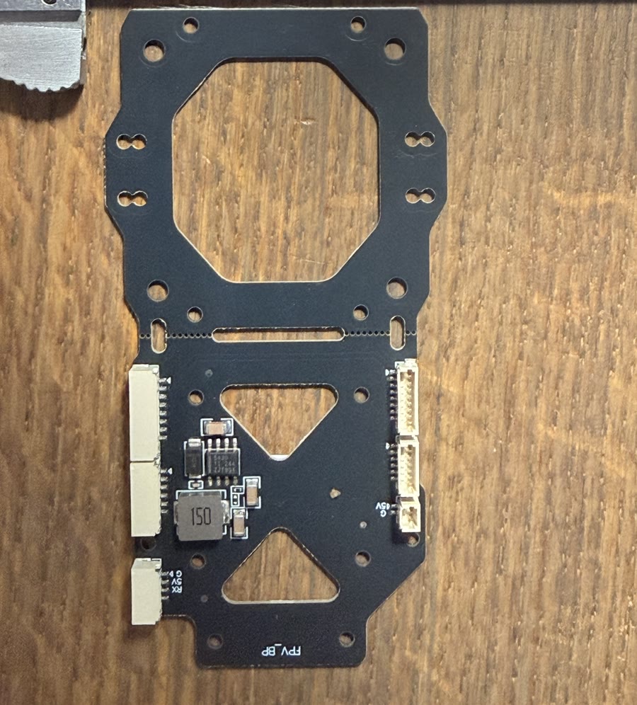
Full pinouts: FPV Gimbal (XF C-20T).
Power from the flight pack
Section titled “Power from the flight pack”We join both Power In and GND pairs into one 4S balance plug, using only its two outer pins: GND and full pack voltage. Check them with a multimeter before you solder.
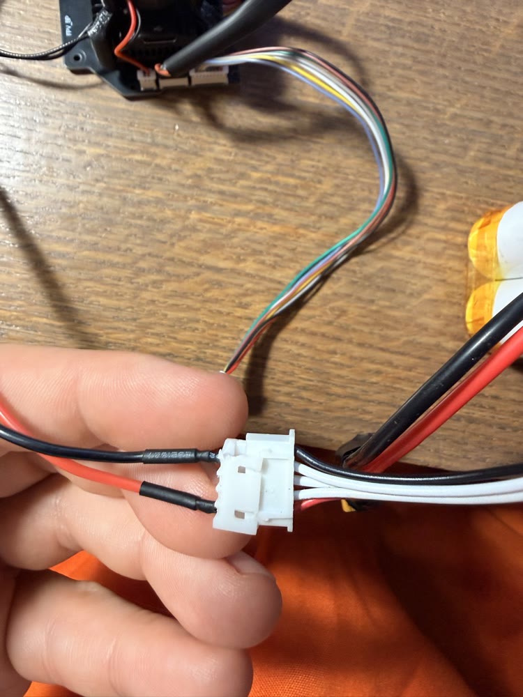
A Y-tap off the XT60 does the same job and switches off with the main plug. We haven’t flown that variant.
Stay off the ESC’s BEC. Its 7.4 V is the gimbal’s lower limit, and the same BEC feeds the flight controller and the swash servos.
Check the common ground
Section titled “Check the common ground”Measure between the pack negative and the gimbal GND. It must read 0 V. A balance plug seated one pin off left our FPV ground 4.1 V high: everything powered up, the signal looked right, and the gimbal ignored it.
Two signals from the flight controller
Section titled “Two signals from the flight controller”The servo rail on the ROBAN X2, top to bottom as printed on the case:
| Label | Output | Used for |
|---|---|---|
| SWA1, SWA2 and the socket below them | 1 to 3 | Swash servos |
| TAIL | 4 | Tail ESC |
| AUX2 | 5 | Free |
| LED | 6 | LED controller |
| AUX1 | 7 | Accessory |
| MAIN | 8 | Main ESC |
| Two unlabelled sockets | 9 and 10 | Gimbal yaw and pitch |
| Two blue sockets | none | Not PWM outputs, leave them alone |
| RX | RC input | S.BUS from the receiver |
Take a 3-pin servo plug and turn it sideways, so two of its contacts sit on the signal pins of outputs 9 and 10. The signal row is the yellow one. The plug carries only those two wires, with no red and no ground, because ground is shared through the pack. Zip-tie the plug so vibration can’t walk it off the pins.
Camera cable
Section titled “Camera cable”Run the coax between the gimbal and the air unit with slack. A tight coax bypasses the gimbal’s dampers, and it’s the usual cause of a jerky pitch axis.
The plate has a 5 V connector for the air unit’s fan.