
DIY Kit Assembly
About 30 minutes and no soldering. Everything screws together.
Two parts are not in the kit and you need them before you can finish: a Raspberry Pi Zero 2 WH and a microSD card. Both are specified below, and the wrong Pi will not work.
Two tools do the whole build: a 2 mm hex key (5/64”, marked .078” on imperial sets) for the kit’s screws, and a 5 mm nut driver for the hub’s copper standoffs.
Both top plates are in the kit, so you can build with or without the 2” screen. Swapping them later is a five-minute job.
What’s in the kit
Section titled “What’s in the kit”Every part travels in its own zip bag with a code on the label, and those codes are used in every step below. For standoffs and screws the number is the length in millimetres — D30 is a 30 mm standoff, S6 is a 6 mm screw. If a bag ever tears you can identify a loose part with a caliper.
Counts include spares — one extra standoff in each set, four extra screws. Leftovers at the end are meant to be there.
| Code | Part | Qty |
|---|---|---|
M1 | Mainboard PCB — buck converter, buzzer, all inputs and outputs | 1 |
H1 | USB Hub HAT, 4 ports (Waveshare) — in its own box with its copper standoffs and screws | 1 |
P1 | Top plate with the screen cut-out | 1 |
P2 | Top plate, solid | 1 |
P3 | Base plate | 1 |
D14 | Standoff M2.5 × 14 mm, short thread | 5 |
D11 | Standoff M2.5 × 11 mm | 5 |
D12 | Standoff M2.5 × 12 mm | 5 |
D30 | Standoff M2.5 × 30 mm | 5 |
S6 | Screw M2.5 × 6 mm | 20 |
K1 | Jack-to-jack cable, 3.5 mm — carries the output to your radio or module | 1 |
E1 | 2” IPS screen, Display HAT Mini — only if you ordered the Screen Add-on | 1 |
T1 | Fox sticker | 1 |
What you need to buy
Section titled “What you need to buy”Raspberry Pi Zero 2 WH — this exact model
Section titled “Raspberry Pi Zero 2 WH — this exact model”Buy a board sold as Raspberry Pi Zero 2 WH. Every letter in that name matters, and boards with very similar names will not do the job:
- 2 — the second generation, with a quad-core Cortex-A53 at 1 GHz. The original Pi Zero and Pi Zero W are single-core, and Magic Box runs the Web UI, the USB stack and the RC output loop at the same time. One core cannot keep up.
- W — wireless. You control Magic Box from a phone or a laptop over Wi-Fi.
- H — headers already soldered on. The Pi plugs into the mainboard through a 40-pin header, and this kit has no soldering step. A Zero 2 W without headers means soldering that header yourself.
A Pi 3 or Pi 4 will not fit the enclosure either. The board you want carries a BCM2710A1, 4 × Cortex-A53 at 1 GHz, 512 MB RAM, 2.4 GHz Wi-Fi and Bluetooth 4.2. It costs around $20.
microSD card
Section titled “microSD card”16 GB minimum. The Magic Box image is exactly 8.00 GiB and an 8 GB card gives you about 7.4 GiB usable — it will not fit.
Bigger is not better. The root partition is not the last one on the card and does not auto-expand, so anything above the image size simply sits unused. 16 or 32 GB is right; a 128 GB card buys you nothing.
Look for the A1 rating. A1 describes small random reads and writes, which is what Linux does all day. Class 10 and UHS-I only describe sequential video recording and tell you nothing useful here.
What we ship in the assembled Magic Box: ADATA Premier microSDHC 32 GB, A1, V10 (part AUSDH32GUICL10A1-RA1). Rated −25 to 85 °C, which is worth having in a model aircraft.
RF transmitter module — your own
Section titled “RF transmitter module — your own”Anything that takes PPM, SBUS, IBUS or CRSF — ExpressLRS and 4-in-1 multiprotocol modules alike. On v2.0, CRSF runs with every module, ExpressLRS and TBS Crossfire included. A classic radio with a 3.5 mm trainer port works just as well. The K1 cable that connects it is in the kit, so there is nothing else to buy here.
A 3S to 6S LiPo with an XT60 connector. Do not try to run Magic Box from a USB port: a full HOTAS setup draws more current than USB will supply and the Pi browns out during boot. The symptoms look exactly like a dead device — no screen, no Wi-Fi, no output.
- 2 mm hex key — 5/64”, marked .078” on imperial sets. This drives every
S6screw in the kit. - 5 mm nut driver — for the copper standoffs that come with the USB hub HAT. You need it in step 1.
- A computer with an SD card reader.
Build it
Section titled “Build it”Eleven steps. Work on a clean surface — the screws are small and the acrylic scratches.
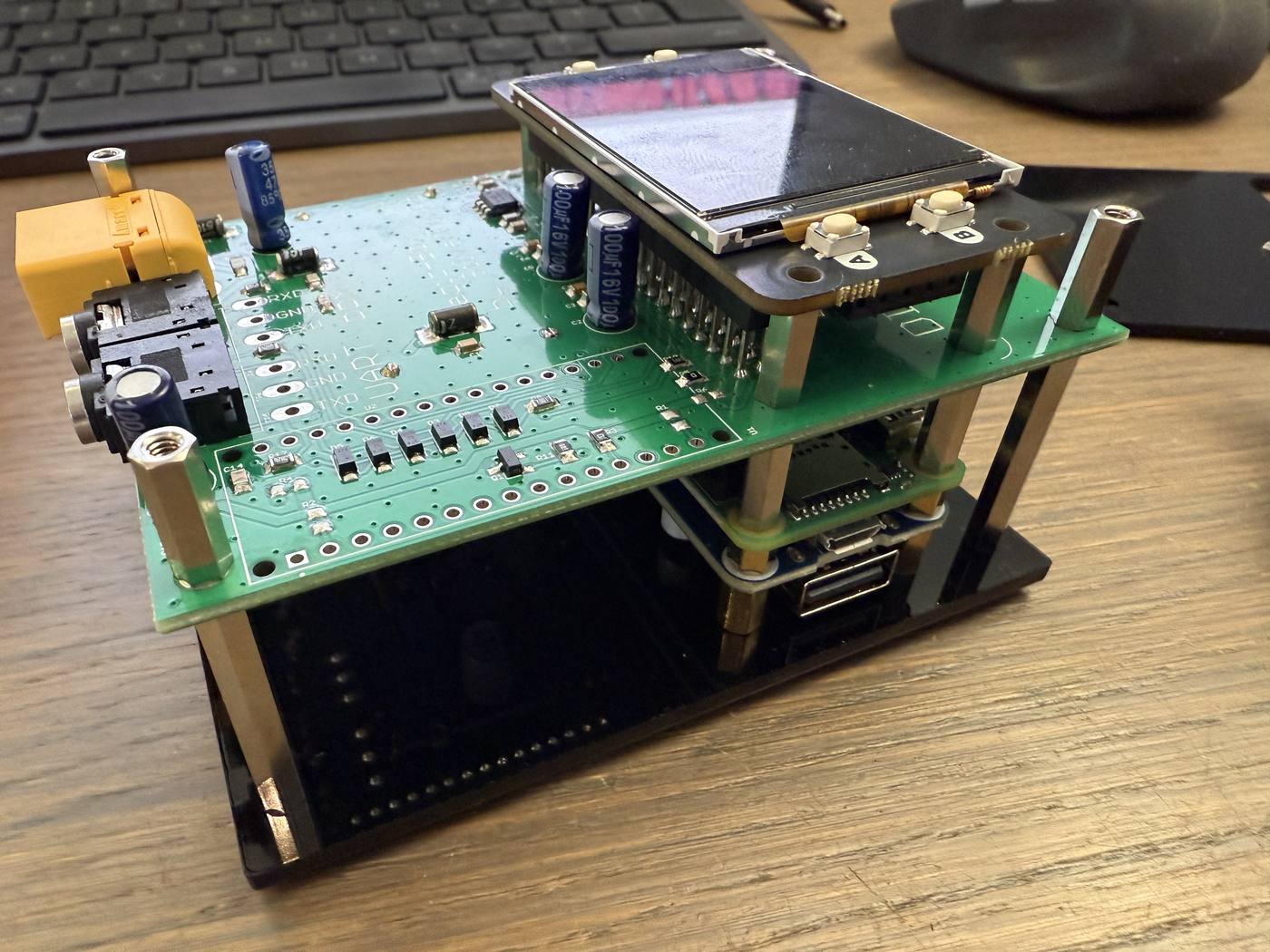
-
Assemble the USB hub (
H1). Screw the hub HAT together using the copper standoffs that came in its own box.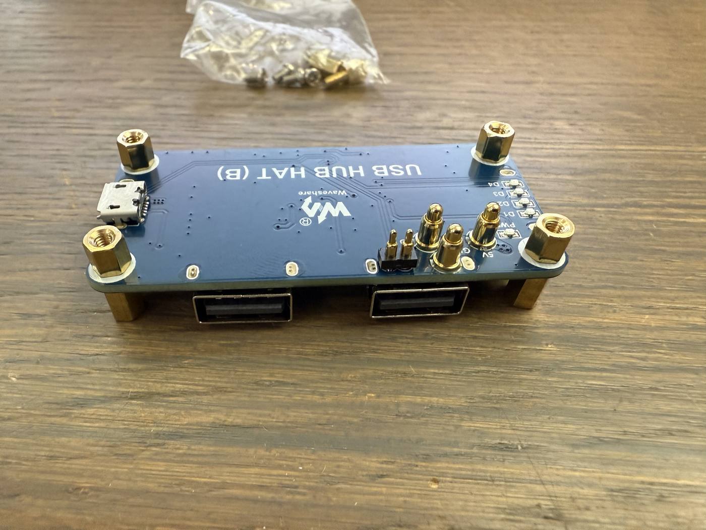
-
Mount
H1on the Raspberry Pi using fourD14standoffs. TheD14standoffs have a shortened thread so that they seat under the hub’s own 4 mm copper standoffs.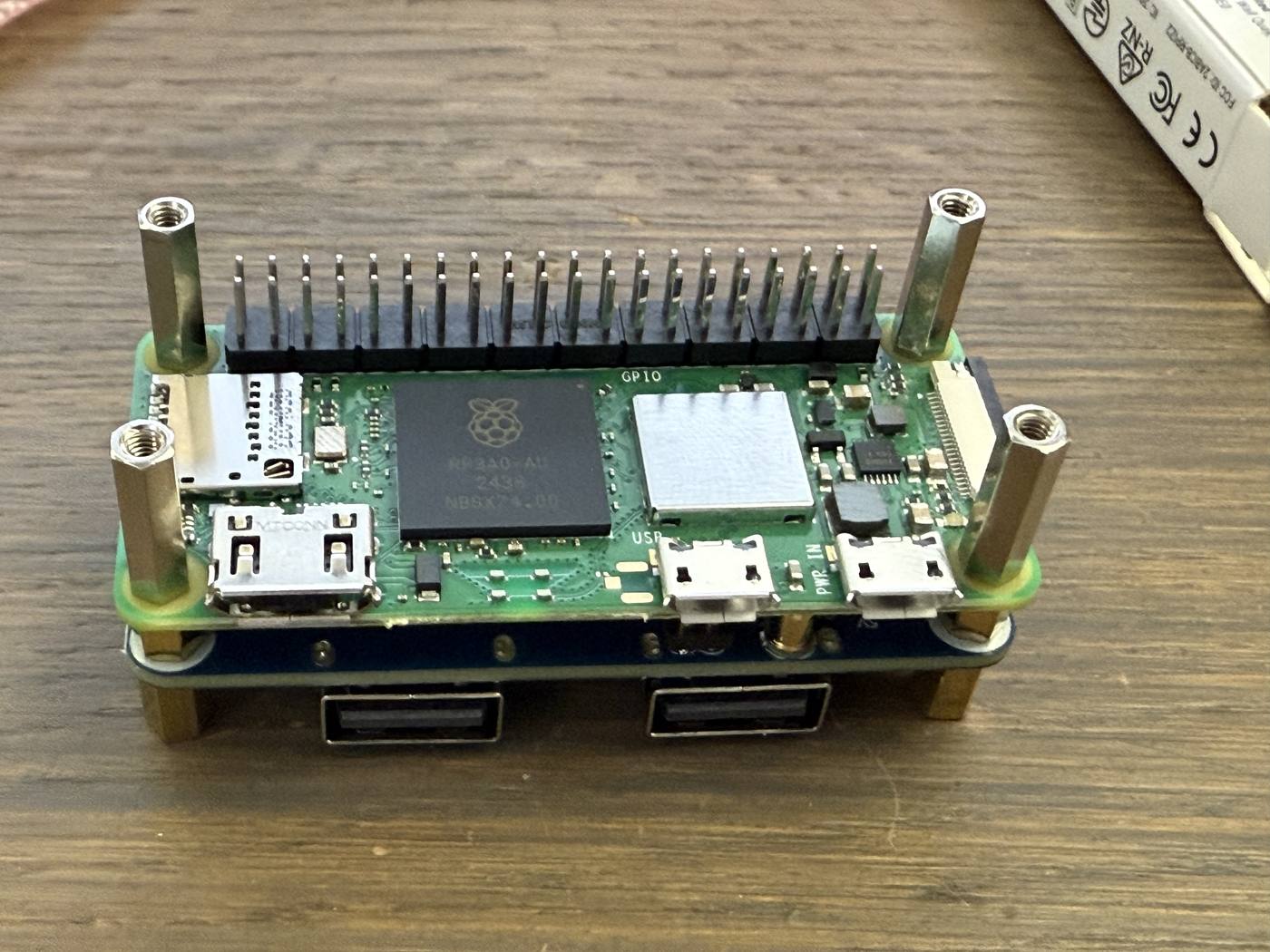
-
Plug the Raspberry Pi into the mainboard
M1through the 40-pin connector. Line the connector up before you press — the pins bend easily.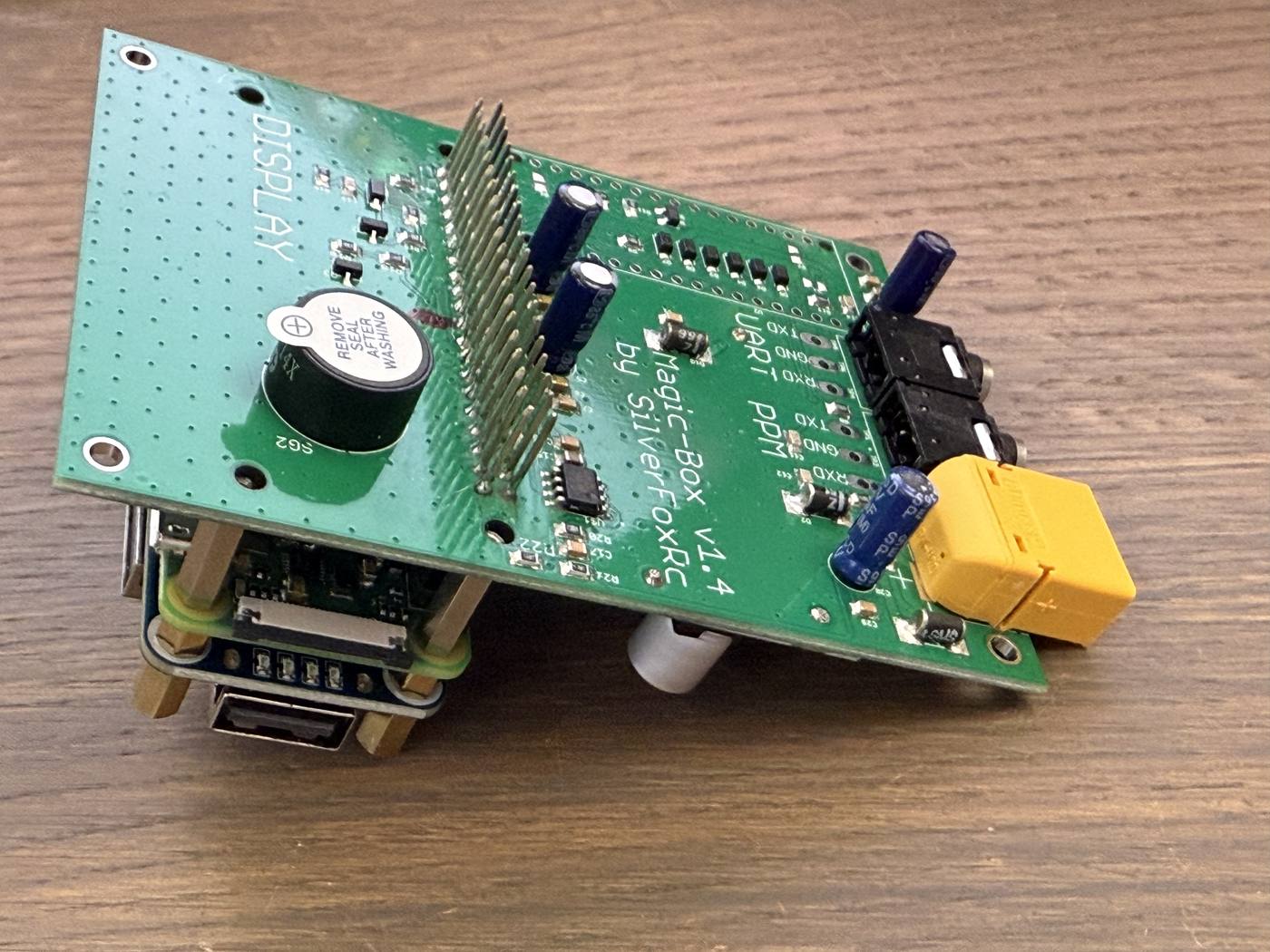
-
Screw
M1down to the Pi with the fourD11standoffs. -
Fit the screen
E1onto the 40-pin connector. On v2.0 the display uses the standard Pimoroni pinout: no modification and no extra wire. Skip if you are building without the screen.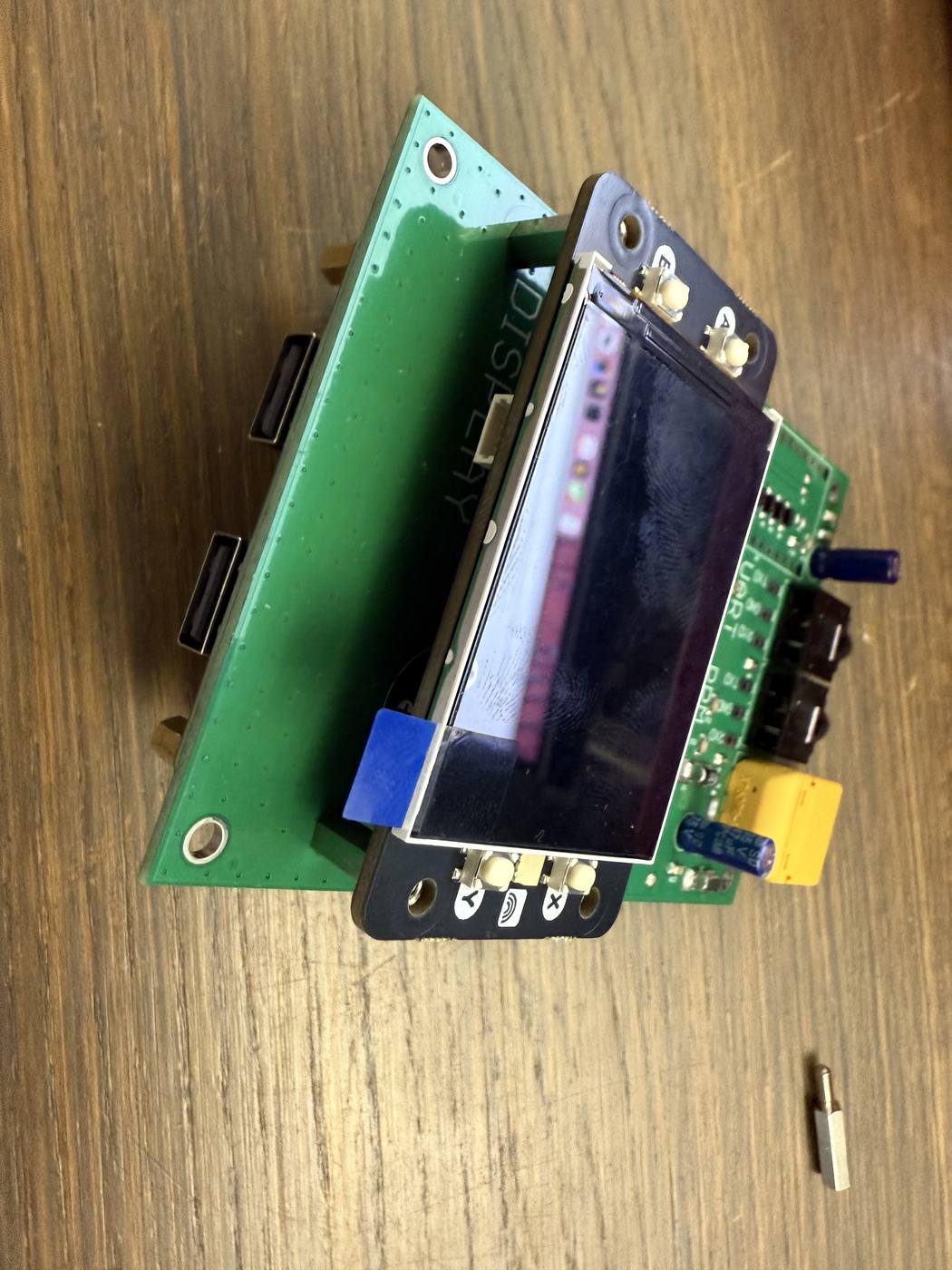
-
At the four corners of
M1, screw aD30standoff into aD12standoff. These are the posts that set the height of the enclosure.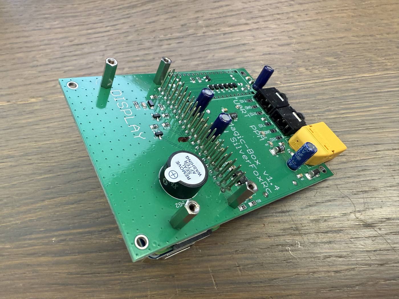
-
Peel the masking film off all three plates — it is on one side only. Picking it off once the plates are bolted into the stack is far more annoying.
-
Fit the base plate
P3from below with 8 ×S6. The lettering faces outwards.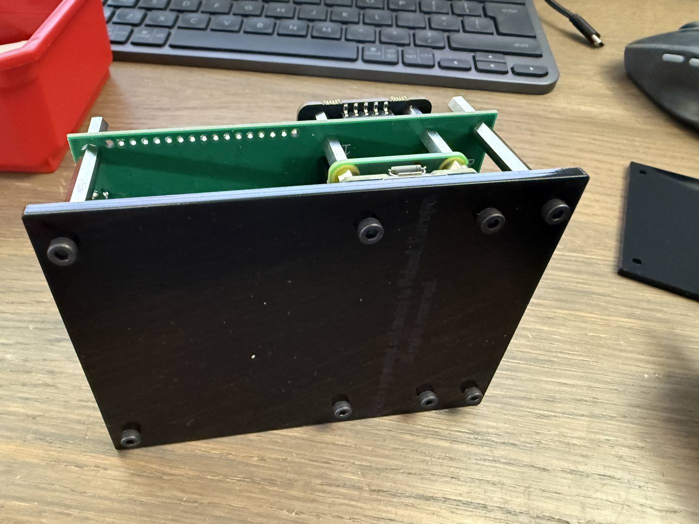
-
Screw the screen down with 4 ×
S6. Skip if you built without the screen.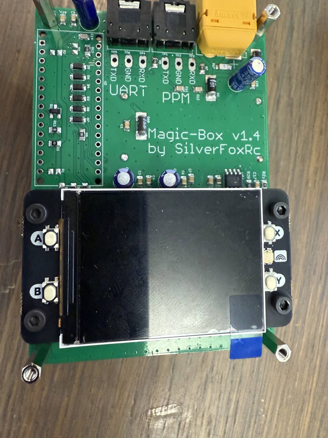
-
Fit the top plate from above with 4 ×
S6, lettering outwards again. UseP1if you fitted the screen andP2if you did not — and keep the other plate.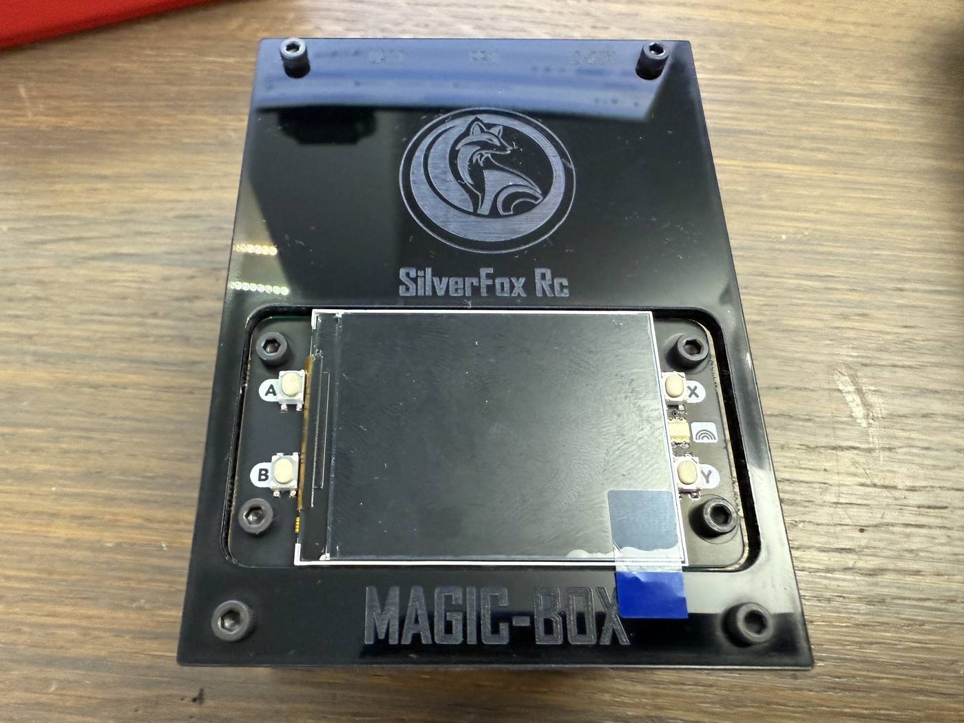
-
Write the SD card and put it in the Pi — next section.
Write the SD card
Section titled “Write the SD card”Download the Magic Box OS image from OS Images, write it to the card with Raspberry Pi Imager, then put the card into the Pi.
How to Update has the walkthrough — it is the same one you will use for every update from here on.
First power-up
Section titled “First power-up”- Switch it on. Magic Box v2.0 has a physical power switch.
- Power it from a 3–6S LiPo on the XT60, not from USB.
- Within about 30 seconds the screen shows a URL. Skip this if you built without the screen.
- Magic Box makes its own Wi-Fi network. Look for an open network named
MagicBox-XXXX, join it, then openhttp://magic.box(or10.11.12.13). It does not join your home network, so there is no point looking for it there. - Connect the output with the supplied
K1cable. Either of the two 3.5 mm PPM sockets will do — they are wired in parallel, so it makes no difference which one you use. The third socket is the UART output, for SBUS, IBUS and CRSF. An RF module should light up blue. - Connect a joystick and move it in circles. Ailerons and elevator should follow smoothly.
If something does not work
Section titled “If something does not work”Work down the list.
- Is it switched on?
- Is it running from a battery rather than USB?
- Screen still dark after 30 seconds — check that the card is written correctly and pushed fully into the slot.
- Cannot find the Web UI — you are almost certainly looking on your home network. Join the
MagicBox-XXXXnetwork first. - Everything is up but the radio sees no signal — open Settings → Output → PPM Pin in the Web UI and switch it. FlySky radios read the Ring contact, RadioMaster and EdgeTX read Tip. Re-select the value even if it already looks right: it is only stored when it actually changes.
Still stuck? Email pmg at silverfoxrc.com.
Where to go next
Section titled “Where to go next”Your Magic Box is now the same device we ship assembled, so the rest of the documentation applies unchanged:
- Quick Setup — wire it into your radio and see a servo move.
- Supported Devices — load a ready-made profile for your HOTAS.
- Output Signals — PPM, SBUS, IBUS or CRSF, and how to pick.
- Hardware v1.4 vs v2.0 — what changed on the board you just built.