
Step 6: OSD in the goggles (optional)
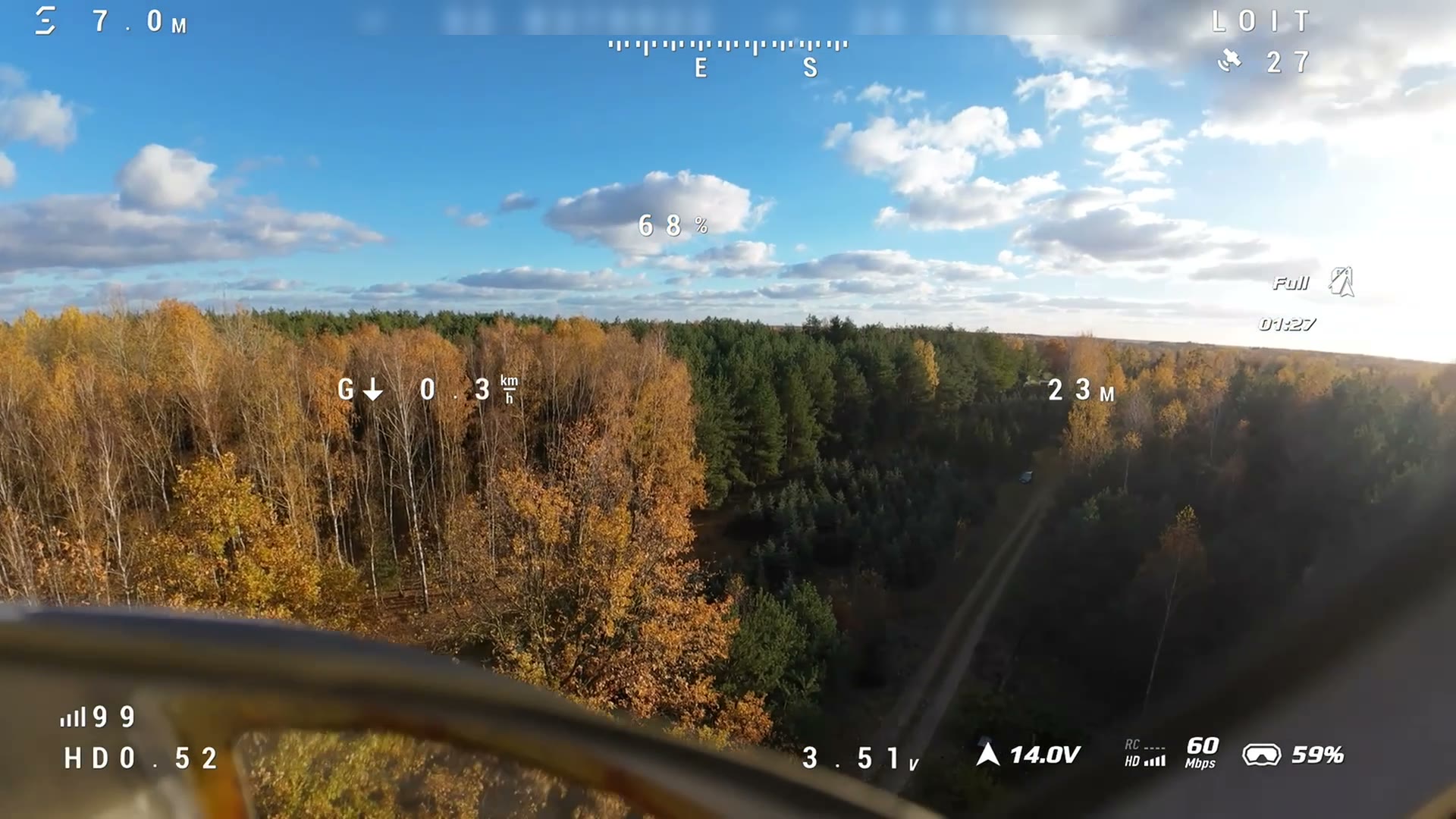
This step is optional. Head tracking and video work on the helicopter’s factory firmware. Do this step if you also want altitude, speed, GPS and cell voltage from the flight controller in your goggles.
How this firmware was made
Section titled “How this firmware was made”The factory firmware has no MSP, which DJI OSD needs, and the standard ArduPilot image for this board leaves it out to fit in 1 MB of flash. So we built our own on custom.ardupilot.org: official ArduCopter Heli 4.5.6 (git 7ce11b41), board QioTekAdeptF407, the server’s default features plus MSP, MSP DisplayPort and Rally, without Airspeed. No code changes, only a different selection of features.
| File | |
|---|---|
| arducopter-heli-4.5.6-msp-qiotekadeptf407.apj | Ready to flash |
| build_request.json, extra_hwdef.dat | Exact build configuration |
SHA-256 of the firmware: 1ca0c7a942b9e59c4f990789383180919378b1e8b9c1e014196035e9012fdf33
ArduPilot is GPLv3. Source: tag Copter-4.5.6. This image is for the ROBAN X2 / QioTek Adept F407 only.
Flash it
Section titled “Flash it”This step needs a command line: Python and a copy of ArduPilot at tag Copter-4.5.6. If that’s new to you, skip it. Have the helicopter on USB only, without the flight battery.
- Save your way back. A full parameter file (Mission Planner: Full Parameter List, Save to file) and a copy of the factory firmware with ArduPilot’s
Tools/scripts/uploader.py --download. That copy is a raw.bin: pack it into an.apjand compare it byte for byte with the download. - Flash the
.apjwithuploader.pyfrom the same ArduPilot tag. - Restore your parameters, reboot, restore again. Some battery parameters only appear after a reboot. Use Mission Planner: Full Parameter List, Load from file, Write Params. Don’t edit the saved file, because rounded values corrupt the sensor IDs. We used our own script, so this exact route is untested on this board, which is why the final bench check comes next.
- Before anything else, run the final bench check. A wrong board orientation shows up there, and not in the air.
To go back, flash the packed factory copy and restore the same file. We made this copy but have never had to use it.
The DJI plug on the base plate fits UART2 on the X2 mechanically, but not electrically. Plugged straight in, it shorts the flight controller’s TX to ground. Re-pin it:
| UART2 on the X2 | Base plate port 2 |
|---|---|
| Pin 2, TX | Pin 3, air unit UART Rx |
| Pin 3, RX | Pin 4, air unit UART Tx |
| Pin 6, GND | Pin 2 or 5, GND |
| Pin 1, +5 V | Not connected |
The air unit takes its power from the pack. Leave DJI HDL unconnected, and find pin 1 with a multimeter.
Parameters
Section titled “Parameters”| Parameter | Value | Why |
|---|---|---|
SERIAL2_PROTOCOL | 42 | DisplayPort on UART2 |
SERIAL2_BAUD | 115 | |
OSD_TYPE | 5 | MSP DisplayPort |
OSD1_TXT_RES | 1 | HD grid, 50×18 |
MSP_OPTIONS | 4 | Betaflight font symbols. With 0 the goggles drop decimals: 16.0 V shows as “1 V” |
OSD_OPTIONS | 17 | No crosshair |
OSD1_CRSSHAIR_EN, OSD1_HORIZON_EN | 0 | The camera follows your head, so a horizon line would mislead |
OSD_CELL_COUNT | 4 | Auto-detection miscounts Li-ion |
OSD1_AVGCELLV_EN, OSD_W_AVGCELLV | 1, 3.4 | Average cell voltage on screen, warning below 3.4 V |
RSSI_TYPE, RSSI_CHANNEL | 2, 14 | Signal strength from the FRM303 |
Turn on the other panels you want with OSD1_name_EN (ALTITUDE, GSPEED, GPSLAT, GPSLONG, HOMEDIR and so on) and place them with _X and _Y.
Restart the flight controller, then turn on Custom OSD in the goggles. The cross in the centre of the picture comes from the goggles: Settings, Camera, Gridlines, Center Point.
Reading it before take-off
Section titled “Reading it before take-off”The flight-mode text carries an armed or disarmed symbol, the satellite count blinks until the GPS fix is good, the home arrow appears once home is set, and pre-arm messages show on screen.