External TX modules
Building a model with an external TX module wired straight to Magic Box (no radio in between)? Magic Box drives the module from one of its two output jacks — UART (digital) or PPM (analog) — and the module talks its own RC protocol on the air.
| Module | Input on the module side | What to set in the Web UI |
|---|---|---|
| ImmersionRC Ghost JR | SBus or GHST (auto-sense) | Output protocol: SBUS |
| TBS Crossfire JR / Nano | CRSF only | Output protocol: CRSF |
| ExpressLRS Lite / JR / Bandit family | CRSF only | Output protocol: CRSF |
| Flysky FRM303 | PPM or SBUS via accessory cables | PPM jack or SBUS output (depending on cable) |
Some JR-bay modules (like the ImmersionRC Ghost) auto-sense the protocol on their input pin — SBUS from Magic Box works fine. Crossfire and ELRS modules are CRSF-only on the input, so Magic Box must output CRSF for those. Either way, no per-module firmware support is needed in Magic Box — set the matching output protocol in the Web UI and the module handles the air protocol on its own.
Examples — module pinouts vary
Section titled “Examples — module pinouts vary”JR-bay modules use the same physical 5-pin connector but different vendors map signals to different pins. There is no universal “JR pinout” you can rely on without checking your module’s docs. Three real-world examples:
RadioMaster Bandit Micro (900 MHz ELRS) — 5-pin standard JR bay, top to bottom on the connector:
| Pin | Function |
|---|---|
| 1 (top) | PPM input |
| 2 | TXC (CRSF telemetry / trainer) |
| 3 | VBAT — power, DC 6 – 16.8 V (from XT30) |
| 4 | GND |
| 5 (bottom) | CRSF input |
Note that PPM and CRSF land on separate pins (1 and 5) — wire to the one matching the protocol you’re outputting from Magic Box. (Bandit Micro user manual PDF)
ImmersionRC Ghost JR — 5-pin JR connector. Per the ImmersionRC manual, top to bottom:
| Pin | Function |
|---|---|
| 1 (top) | PPM — signal input |
| 2 | N/C |
| 3 | VBatt — battery voltage in (6 – 20 V per ImmersionRC spec) |
| 4 | Gnd |
| 5 (bottom) | S.Port — SmartPort telemetry |
The pin labeled “PPM” is the signal input; per the ImmersionRC spec sheet, this input auto-senses PPM, SBus or GHST, so SBUS from Magic Box works without further configuration on the module side. The module’s air protocol stays GHST regardless of what you feed it on the input.
Flysky FRM303 — not a JR-bay module. Uses its own Signal Interface connector plus two accessory cables that ship in the box, each carrying a different signal type:
| Accessory cable | Signal | Plug into Magic Box’s |
|---|---|---|
| FS-XC503 — 3.5 mm audio jack cable | PPM | PPM jack (no Web UI configuration) |
| FS-XC505 — DV / bare-wire cable | S.BUS / UART | UART jack (Web UI → output protocol SBUS on v1.4) |
So there’s nothing to wire on the JR connector — the FRM303 doesn’t have one. You pick the cable that matches the Magic Box jack you’re using and plug both ends in. Power is separate, with three options selectable via a 3-position switch on the module body (Int / Off / Ext): internal Li-Po, USB-C (4.5–5 V DC), or XT30 external (5–28 V DC per Flysky spec — 2S through 6S LiPo all accepted).
The takeaway: pinouts vary across vendors, product lines and even revisions. The two pins you actually need to find on your module are signal in (matching the protocol you’re outputting from Magic Box) and GND. Power either comes from a separate connector (XT30, JST, leads) or from one of the JR pins — your module’s manual will spell it out.
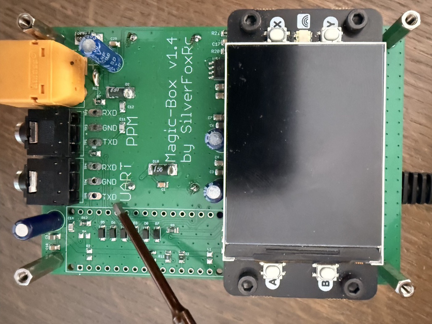
Wiring — use the included stereo cable
Section titled “Wiring — use the included stereo cable”Every Magic Box ships with a 3.5 mm stereo cable. Plug it into the UART jack on the side of the case (the upper of the two jacks — silkscreened UART) and you’ve got the UART signals broken out on the other end of the cable, no soldering on the Magic Box side:
| Cable contact | UART signal | What it’s for |
|---|---|---|
| Tip | TXD | Output signal — whatever digital protocol you set in the Web UI (on v1.4, this means SBUS) |
| Ring | RXD | Telemetry input from the module (optional — only if your module sends telemetry back on the same wire) |
| Sleeve | GND | Shared ground |
Cut the other end of the cable, strip the three conductors, and run them to your TX module. The two wires that matter are signal and ground:
- Tip wire → module’s signal input pin. Look it up in your module’s docs — labels vary (“SBus in”, “PPM in”, “CRSF in”, “trainer in”), but it’s the pin a radio would drive to talk to a seated module. JR-bay modules generally follow the same physical pinout, but always verify against your module’s spec sheet before wiring. Heads-up: some modules expose separate input pins for analog (PPM) and digital (SBUS / CRSF) — Flysky FRM303 is one example. If yours does, plug the cable into Magic Box’s UART jack for digital, or PPM jack for analog, and wire to the corresponding pin on the module.
- Sleeve wire → module GND. Always there, always needed.
- Ring wire — leave it, or wire it back to your module’s telemetry output if it has one. Most pilots don’t need this.
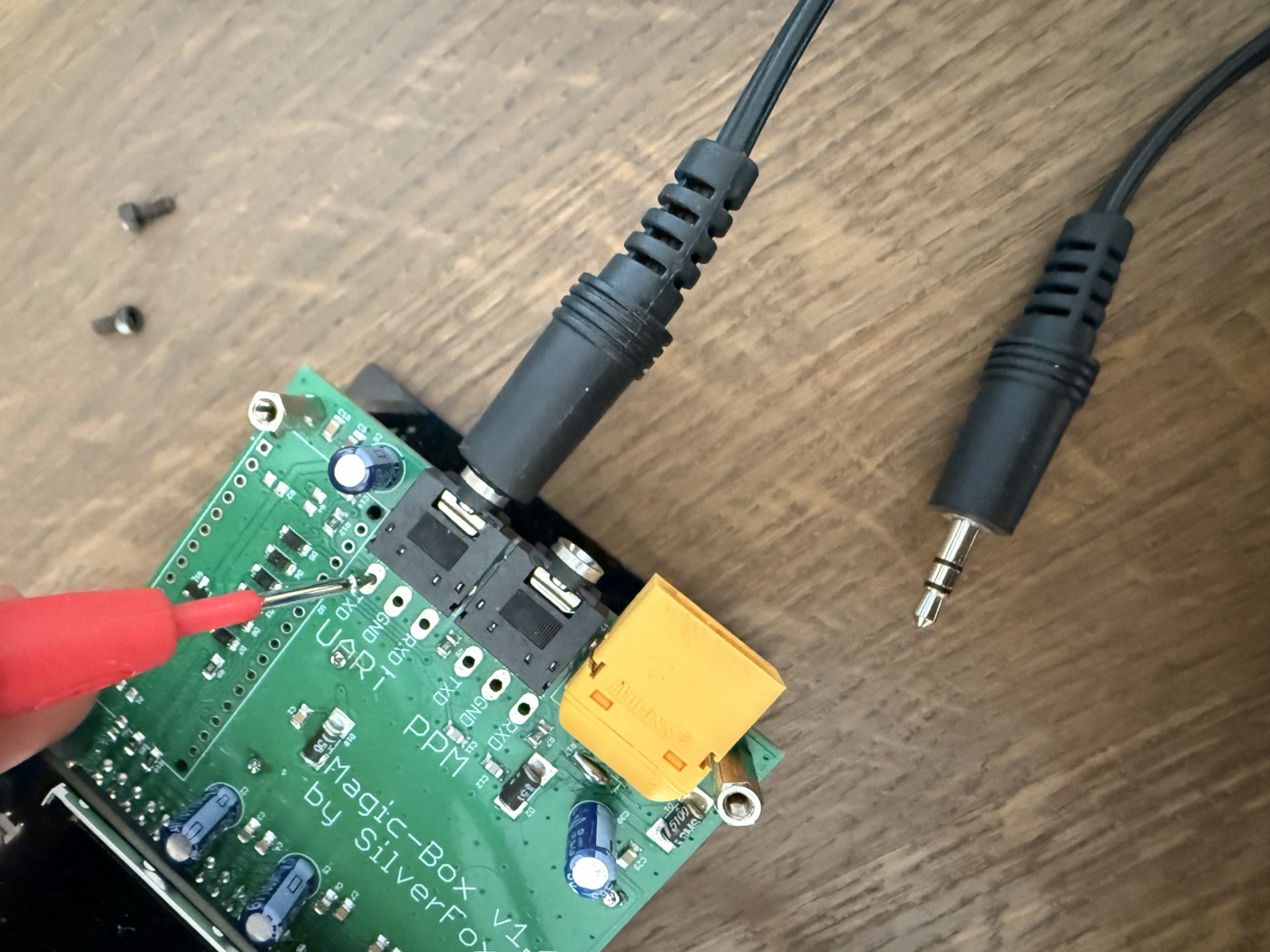
Wire colors inside the cable aren’t standardized across batches. Buzz it out with a multimeter (continuity mode) against the still-attached plug to identify which conductor is tip, ring and sleeve. On a 3.5 mm stereo plug, the three metal sections — from the very end of the plug down to the body, separated by black plastic rings — are tip, ring and sleeve in that order.
Wiring — solder to UART pads (alternative)
Section titled “Wiring — solder to UART pads (alternative)”Some TX modules ship with their own pigtail — a connector on the module side and bare wires on the other end. If you’d rather use that cable than cut the included stereo one, you can solder the bare wires straight to the UART pads on the PCB.
Open the case (four screws), find the UART block, and solder:
- Module input pin (signal) → TXD pad
- Module GND → GND pad
- Module telemetry output, if used → RXD pad (optional)
Once the wires are in, route them out of the case and reassemble. A small notch in the case wall keeps things tidy if you don’t want them sharing the jack opening.
The module needs its own power supply. JR-bay modules typically expect roughly 6–15 V on the supply pin (the range a radio’s bay socket provides) — but the upper limit varies module-to-module, so check your module’s spec sheet before picking a battery. A 4S LiPo (16.8 V fully charged) is above the rated input for many modules. Two clean ways to do it:
Option A — Y-cable off your flight battery (simplest)
If your module has its own power connector (XT30, JST, bare leads):
- One LiPo — typically 3S (12.6 V max), or 4S only if your module supports it (verify the spec).
- Y-splitter: one branch to Magic Box, one to the TX module.
- No separate BEC, no second battery, no extra regulator. Both share the same source.
Option B — DC-DC tap from inside Magic Box
If your module doesn’t have an external power connector, you can tap power from the DC-DC step-down converter inside Magic Box. Open the case (four screws), find the small blue daughterboard near the edge of the motherboard:
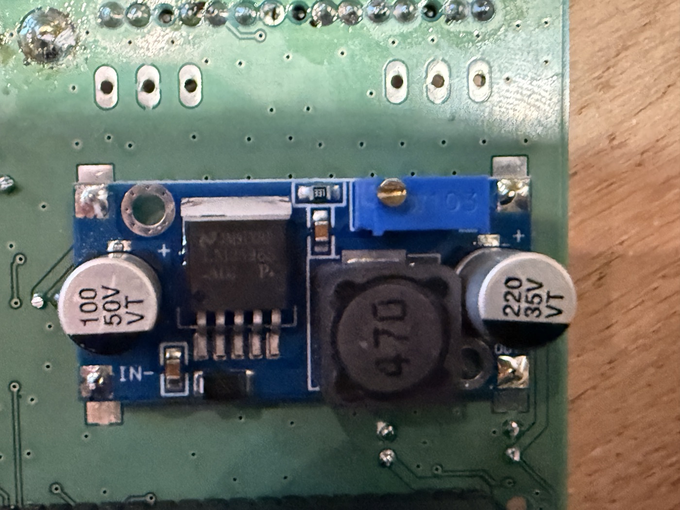
The daughterboard has solderable pads on both sides:
- IN side (left) — raw battery voltage from your LiPo (whatever it’s putting out: roughly 11–25 V for 3S–6S). Look for the IN- silkscreen mark; IN+ is the matching pad on the same edge.
- OUT side (right, near the motherboard edge) — regulated 5 V, which powers the Raspberry Pi. Don’t tap here for an external module — most JR-bay modules need at least 6 V on their supply pin and won’t start up off 5 V.
For a Ghost / Crossfire / ELRS module, solder a pigtail onto the IN side (battery voltage). One battery now powers Magic Box and the module, no XT30 needed.
Magic Box configuration
Section titled “Magic Box configuration”In the Web UI:
- Settings → Output protocol → pick the protocol from the table above (e.g. SBUS for Ghost, CRSF for ExpressLRS / Crossfire). If you’re using the PPM jack instead, no Web UI configuration is needed — PPM is always on.
- Save. The change applies on next boot.
Map your HOTAS channels in the active profile the way you would for any other receiver — they go out on the wire on the protocol you picked, the module reads them off its input pin, and the receiver picks them up on the air.
Verify before you fly
Section titled “Verify before you fly”The Web UI’s live channel view shows what’s going out on every channel. Move your HOTAS axes, watch the channels respond. Then bind your receiver to the module the way you’d bind any GHST / Crossfire / ELRS link. Channel motion in the Web UI and matching motion on the receiver = chain is good.
Different module that’s not in the table above? Drop a note in the community group — if the spec sheet says it auto-senses SBus or CRSF on its input, it’ll work the same way; we’ll confirm and add it to the table.
- Just picking the right protocol for your radio? See Output Signals overview.
- Want the analog path? See PPM.
- Want the ExpressLRS / Crossfire details? See CRSF.